Posts

Showing posts from March, 2015

BASICS OF SKETCHING

Image
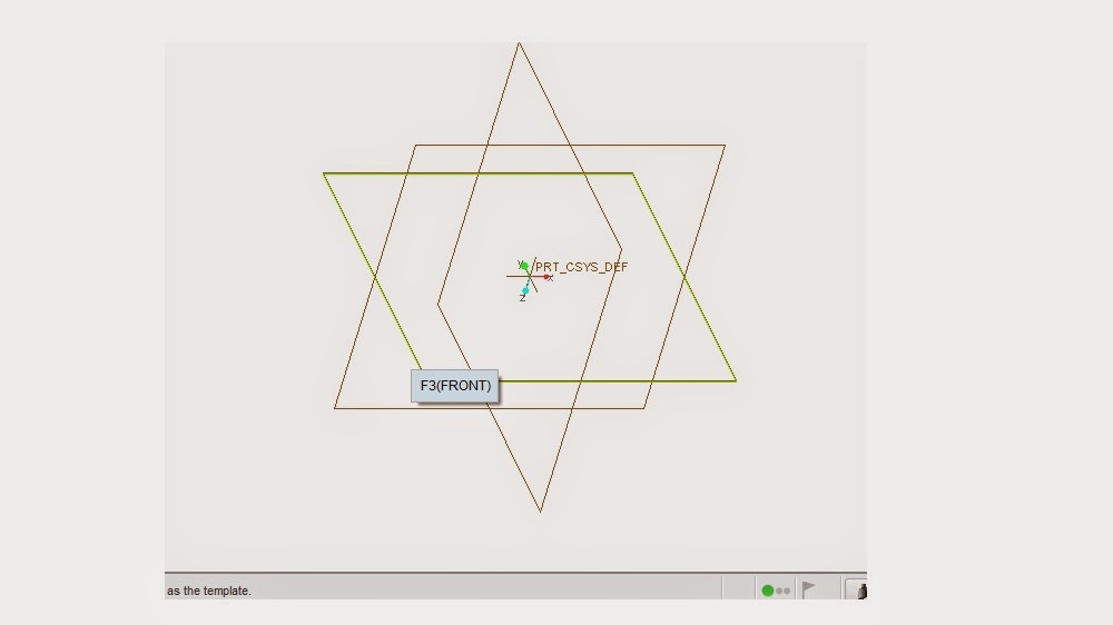
SKETCHING Sketching is a basic process in 3D modeling of a component. For any component a sketching is primary thing. For any model it consists of three planes.   The planes shown above are the three planes of views. The three planes shown are orthogonal in nature i.e., every plane makes an angle 90 0 with each other. To do sketching we have to select any one plane. We do sketching on a plane. Sketching is a 2D.To make it into 3D we use several options like extrude, revolve, sweep etc,.  In order to do sketching on any plane we have to select a plane and it selects a reference plane along with selected plane in order to make into 3D model.            The below diagram shows the sketching plane. The sketch plane consists of different sketching options like Line, Circle, Rectangle, Arc, Ellipse, Spline. The basic drawing options are 1.       Line  -- General line , Tangent line (To draw line between two circles) 2.       Rectangle -- Corner rectangle, Slanted re

ANALYSIS IN PRO-ENGINEER

Image
CANTILEVER       Generally analysis in Pro-E is also called as Mechanica.Today i will explain how we gonna do analysis in pro-e without using structural analysis softwares like Hypermesh and ansys. It is very easy to do in Pro-e rather than ansys but the results obtained here are not accurate.              Today i will explain on a beam of rectangular cross section of 50*30 as area and length as 250mm.It is very easy procedure. The above is the beam i modelled on Pro-E Creo 3.0.In this after creating model in Pro-E we have to go to applications from where we choose Analysis.For better understanding i will explain by points Go to Applications Go to Simulate Choose material for model Create material assignment in down tab After that go to Displacement and select one surface so that we create a constarints The above diagram shows the constaints After that apply loads on surface After that go to Analysis studies and create a new static model. After cr

BASICS OF 3D MODELLING

Image
BASICS OF MODELLING Hi Good Morning to every body, as i posted on Pro-Engineer article i am here to say about basics of modelling. Generally modelling of a 3D model is done from a 2D drawing. These 2D drawings are generally called as Orthographic projections. See the below image In the above image the drawings on right side are orthographic views of the left sided 3D model. These are connected by lines known as projectors. These 3 views are three faces of 3D model.And based on views we can divide them as  First angle  Third angle  First angle is a type of projection in which the object lies between observer and plane.In this projection the object is situated in first quadrant. All Indian standards comes under first angle type In case of third angle the plane situates between object and observer.Object is situated in third quadrant.Third angle is generally used by British standards. Everybody has a doubt how to select type of projection used, but is basica
Pro- Engineer Pro-E is a mechanical design software used in making of 3D models from 2D models.Here the 2D models are known as Orthographic projections. Everybody has an idea of learning Modelling, Sheetmetal, Drawing, Detailing is enough for a Mechanical design engineer.But it is not the right case,but basically i agree with you all, because the students have little knowledge on Industrial exposure. So i am trying to help you.  Here i am not the Professor any more, but i am student like you.It is Just sharing ideas of what you known and what i known.It is just a mutual understanding. The total no of modules in Pro-Engineer are as follows Sketching Modelling Drafting Detailing Advanced Modelling Assembling Sheetmetal Cabling Piping Manufacturing Mechanica Mechanism Animation. If we learn this we will be perfect in Pro-E. So every week i will explain each and every thing, and i am suggesting all the Mechanical engineers to follow and come with